
Colors play a very important role in human daily activities, being tied to several connotations, such as its functions in traffic lights, raiment of a particular profession, entity representation through geometric shapes, human-computer interaction concepts, and others. Such examples denote an universal language that does not sit well with idiomatic languages. Color blindness, however, affects (or even ceases) this sort of asset in communication, which can be explained as abnormal photopigments, located in cone-shaped cells within the retina, called cone cells.
This article is divided in the sections listed above. If you wanna jump to the technical details, check implementation details or download the code at the GitHub repository. Before continuing your reading, check the project video to see what this project is really about :)
Project overview
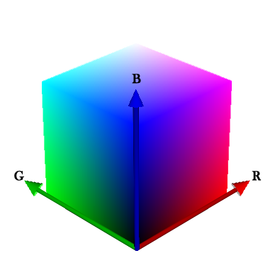
Similar to color vision of the human eye, as well as based in light, the RGB model comprises more than 16 million colors, which are arranged in a 3d space, where integer values of components R (Red), G (Green) and B (Blue), ranging from 0 to 255, constitute coordinates of this space. From this model, color detection and recognition were performed with light-related electronic components and machine learning mechanisms; it is essentially the combination of an RGB LED and a CdS Cell (light sensor, or LDR), both isolated from ambient light. Such components, respectively, emit and sense the intensity of each light (red, green and blue) which was reflected from an object of a particular color.
Color recognition can be performed with machine learning algorithms, such as Multi-Layer Perceptron (MLP) - an architecture of Artificial Neural Networks (ANN). It allows classification and recognition of spatially separable patterns - very useful in this case.
It is important to consider situations when the human eye unsuccessfully attempts to recognize colors due to poor ambient conditions, or even difficulties in distinguishing particular shades of colors. This is comparable to outliers or distorted patterns, which may affect precision in the recognizing task; regarding feature (RGB) space, a misclassified color should be interpreted as a coordinate located at spatial regions associated to another color (sometimes due to poor generalization, overfitting, and many other possibilites).
An MLP, during training, should perform mapping of regions in the RGB color space illustrated below. Each region isolated by hyperplanes represent a color, so every new color pattern located in a particular region is classified as its respective color.

Multi-Layer Perceptron
Multi-Layer Perceptron is a feedforward architecture of ANNs, having an input (non-neural) layer, hidden layers and an output layer. This network is trained by backpropagation algorithm, performing supervised learning (learning by examples).
Topology configuration (i.e., size of each layer) is defined according to a specific problem to be worked on. For this color sensor, as indicated in the MLP Topology Workbench below, the neural network receives 3 inputs (RGB values), having one hidden layer with 6 neurons and an output layer with 10 neurons - just recalling: the output layer must have the same number of classes (colors, in this case), for a binarized output. Hidden-layer sizes are empirically obtained, establishing ranges of values for each topological parameter, so that approaches for Hyperparameter optimization may find potentially good results (this can be a bit difficult and slow sometimes). The network below is already trained and interactive, so it is possible to input values at training tab and check the outputs.
Color recognition
With the purpose of obtaining generalization with an MLP for a good recognition of RGB patterns, a training set (examples of colors with the desired output) must be presented to the network for the training step (download the implemented architecture to perform training). The training set used in this project is available at the project’s GitHub repository.
Generalization will happen within the domain that the training set comprises, so it is worth to pay attention to minimum and maximum values of each component of the space! Do not feed the network with patterns outside this domain, otherwise it would output an unexpected behavior.
The dataset (all examples) contains 75 instances of color patterns ranging from 0 to 1 (logistic activation function was used). Initially ranging from 0 to 255, these instances were rescaled by simply dividing each value by 255, such that \( 0 \leq x_1, x_2, x_3 \leq 1 \). It is important to point out that only one neuron at the output layer must output 1, whereas the remaining ones must output zero. Of course this is not possible using a sigmoid activation function; that’s when post-processing takes place:
\[y_i^{post} = \begin{cases} 1 & \text{, if }y_i=\max(y)\\ 0 & \text{, otherwise} \end{cases}\]where \( y_i \) is the output of the \( i^{th} \) neuron and \( \max(y) \) is the is the greatest output value. In practical terms, the neuron with the greatest output gives 1 as output and the remaining ones give 0. Simple as that.
A trained MLP should create regions in the color space, separating color patterns, as shown below the visualization of the instances of the dataset. Gray color instances are also included for another version of the trained network - but pretend gray instances are not there.
Implementation details
This section is divided in three parts: electronic circuit, color theory and programming. Click the links if you want to jump to a specific part.
Electronic circuit
Arising from objects, all the detection procedure happens in the electronic circuit, encompassing computational activity running in an Atmega328, which is hooked up in an Arduino Uno. Check the scheme below to see the wiring.
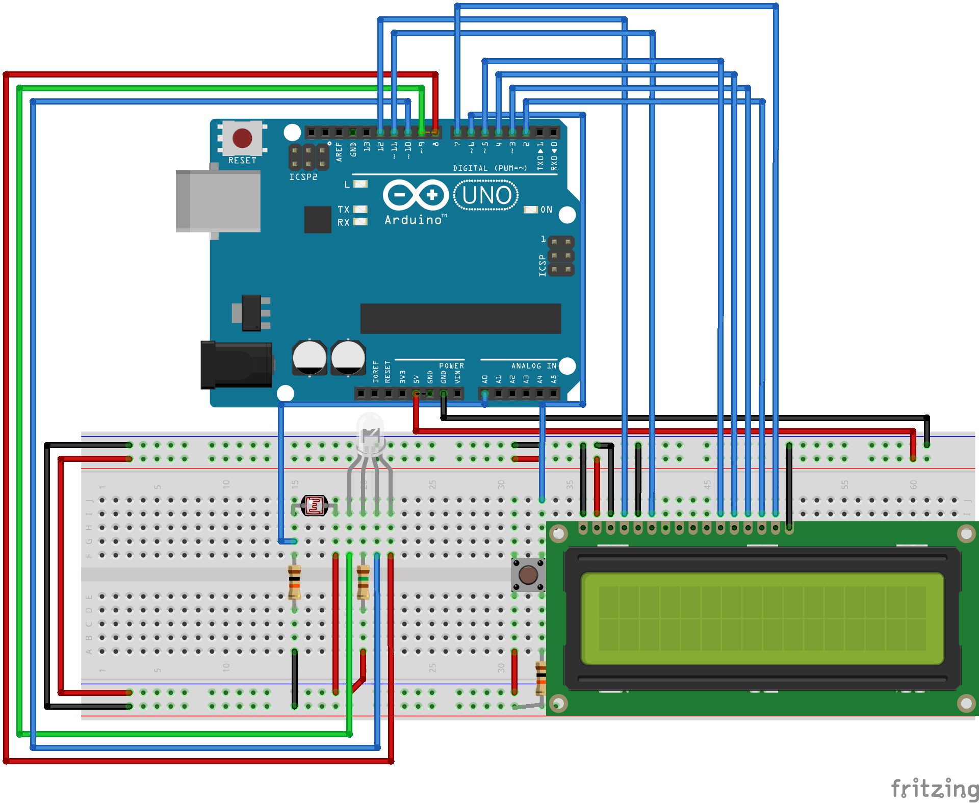
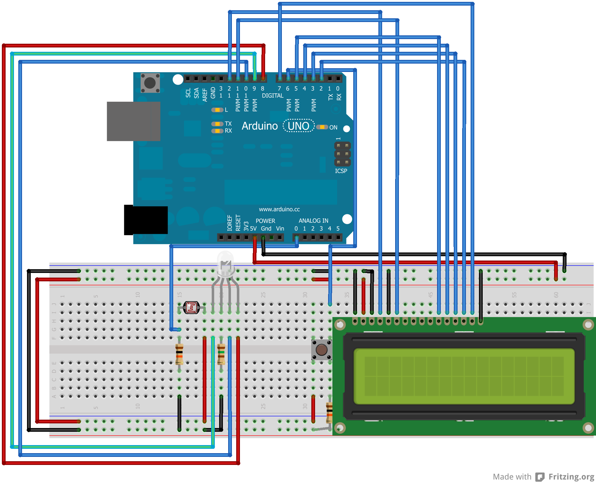
The code follows the scheme that uses a common anode RGB LED, so check whether your RGB LED is also a common anode, otherwise just invert the logic in the code.
Another important detail is that I am using only one resistor with the RGB LED. Since one color at a time will be lit, I put the resistor in the common anode, with an average resistance of the resistors that should have been with the cathodes - it is lazy, I know and I am sorry! When I went to buy project parts, they didn’t have everything I needed - but it is however very important to use the correct resistors with the cathodes in order to have fidelity in the collected RGB values in relation to RGB values in the computer. The way I did is not that bad, since the patterns are not distorted; they are just not the same colors we see in a computer screen.
It can be observed from the scheme an adjacency between the RGB LED and the CdS Cell. That is because they must be isolated from ambient light (an oldie black film tube is the perfect piece), so calibration (explained in Programming) and recognition can be performed.
Color theory
Color perception performed by the electronic circuit is based in color theory concepts. Since there are no lenses (yet) involved, only objects with opaque (and matte) material should be considered, avoiding to deal with specular reflection of the LED. Diffuse reflection on the other hand is the key to perform color detection with lights. From an incident light, it is reflected in irregular surfaces, not creating that glowish effect that ruins the function of the CdS Cell.
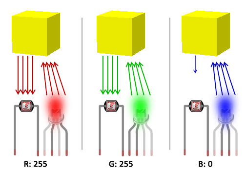
Back to actual color theory, when light (of a certain color) reaches an object, it is reflected according to properties of that object’s color. For example, a red light reaching a yellow object will be reflected according to how much red exists in the composition of that yellow color - remember, we are talking about lights! - so it is expected to have a lot of red light being reflected, what makes sense when we think of the RGB composition of yellow (essentially red and green). However, when a blue light reaches the yellow object, no strong reflection is expected due to low presence of blue in the color composition.
Considering an additive color system, in which white and black are respectively presence and absence of every colors (more details here), there can be measured (with the CdS Cell) maximum and minimum reflections of each light from the RGB LED which will reach colored objects. That said, it is possible to perform the calibration in electronic components involved in the circuit. This is another key to get fidelity in detection, as well as to ensure a stable detection of patterns (avoiding outliers) - here is a golden tip: after calibrating, try (hard!) not to move or touch neither the electronic components (specially when they are placed in a breadboard), nor the piece you are using (you must use) to isolate components from ambient light.
Programming
For calibration and recognition, the color sensor executes three iterations, once a colored object is exposed to the RGB LED and the CdS Cell. In the first iteration, red light hits the object and the program waits CdS cell to stabilize its sensing; the analog input is then read and the reflection of the red light is stored. The program iterates twice more for green and blue colors. The figure shown in Color theory gives a good visual explanation of this iterative process.
Concerning calibration, the iterative process mentioned above is performed twice: once for black color and once for white color. As explained in Color theory, this is for the detection of maximum and minimum - initially from near zero to near 1024, according to the reading resolution - reflections of red, green and blue lights, obtaining a true range to properly rescale to intervals \( [0,255] \) (for informative purpose) and \( [0,1] \) (the actual input to feed the neural network).
The waiting time to establish reading of the light sensor can vary according to each electronic component, so it is good to give a good delay to ensure a steady sensing. In my case, I gave a 500-millisecond delay, but it is worth to initially use a bigger value and then decreasing it until the verge of a non steady behavior.
In detection, the collected RGB values - ranging from 0 to 1 - feed an MLP, performing the actual color recognition. For the MLP running in Arduino, I am using Neurona - a library I wrote to easily use ANNs in arduino. Check also this post for more details; for training MLPs, I am using an implementation in C language (The MLP Topology Workbench also does the job), giving the adjusted weights to use with Neurona. Still regarding training, it was used \( \alpha=0.8 \), \( \eta=0.1 \) and \( \epsilon=10^{-7} \).
Given topologic configuration and the dataset, five trainings were performed (with cross-validation), each one with a random initial state of the synaptic weights:
| Training # | Epochs | Accuracy |
|---|---|---|
| 1 | 1565 | 67% |
| 2 | 2353 | 95% |
| 3 | 3315 | 80% |
| 4 | 4239 | 93% |
| 5 | 680 | 40% |
From a balanced dataset, accuracy was considered to compare training results. Training #2 presented best generalization, being the one to have its weights embedded along with Neurona and the Arduino program.
Tests
Bringing a more practical perspective, some colors were extracted from the dataset to perform some recognition tests:
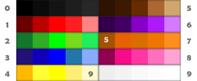
Numbers outside the figure are used for identification and numbers inside the figure indicate misclassifications, referencing which colors were classified instead. These colors were printed in sulfite paper with an inkjet printer - check the tiny paper squares in the video in the beginning of this post - so the objects consist of opaque material, proper for color detection.
comments powered by Disqus